Safety relay for emergency stop, safety doors, light grid up to SIL 3, Cat. 4, PL e, 1- or 2-channel operation, cross-circuit detection, can be retriggered, fall back/on delay 0.2 s ... 60 s, 2 enabling current paths, US = 24 V DC, pluggable Push-in terminal block
Utilization restriction
EMC note EMC: class A product, see manufacturer's declaration in the download area
Product type Safety relays
Product family PSRmini
Application Emergency stop
Safety door
Light grid
Relay type Electromechanical relay with force-guided contacts in accordance with IEC/EN 61810-3
Times
Typical response time < 35 ms (automatic start)
< 30 ms (manual, monitored start)
Typical release time < 25 ms (when controlled via S12 (only for undelayed contact 13/14))
< 5 ms (when interrupted via A1; applicative deactivation via A1/A2 is not permitted)
Delay time range 0.2 s ... 60 s ±5 % (can be set for 27/28)
Restart time < 1 s (Boot time)
Maximum power dissipation for nominal condition 5.78 W (at US = 30 V, IL² = 72 A²)
Nominal operating mode 100% operating factor
Air clearances and creepage distances between the power circuits
Rated insulation voltage 250 V AC
250 V AC
Rated surge voltage/insulation Basic insulation 4 kV: between all current paths and housing
Safe isolation, reinforced insulation 6 kV:
between (A1, A2, S11, S12, S21, S22, S34, M1) and enabling current path (13/14)
between (A1, A2, S11, S12, S21, S22, S34, M1) and enabling current path (27/28)
between enabling current paths
Supply
Designation A1/A2
Rated control circuit supply voltage US 19.2 V DC ... 30 V DC
Rated control circuit supply voltage US 24 V DC -20 % / +25 %
Rated control supply current IS typ. 60 mA
Power consumption at US typ. 1.44 W
Inrush current typ. 25 A (Δt = 10 µs at Us)
Filter time 10 ms (For the logic. At A1 in the event of voltage dips at Us )
Protective circuit Surge protection; Suppressor diode
Protection against polarity reversal for rated control circuit supply voltage
Digital: Sensor circuit (S12, S22)
Description of the input safety-related sensor inputs
Number of inputs 2
Input voltage range "0" signal 0 V DC ... 5 V DC
Input current range "0" signal 0 mA ... 2 mA
Inrush current < 11 mA (typically with US)
Filter time max. 3 ms (Test pulse width of low test pulses)
min. 21 ms (Test pulse rate for low test pulse)
Test pulse rate = 7 x Test pulse width
Concurrence ∞
Limit frequency min. 0 Hz
max. 1 Hz
Max. permissible overall conductor resistance 150 Ω
Current consumption < 4.1 mA (typically with US)
Digital: Start circuit (S34)
Description of the input non-safety-related
Number of inputs 1
Inrush current < 8.6 mA (typically with US)
Filter time max. 3 ms (Test pulse width of low test pulses)
min. 21 ms (Test pulse rate for low test pulse)
Test pulse rate = 7 x Test pulse width
Max. permissible overall conductor resistance 150 Ω
Voltage at input/start and feedback circuit 24 V DC -20 % / +25 %
Current consumption < 3.2 mA (typically with US)
Relay: Enabling current paths (13/14, 27/28)
Output description safety-related N/O contacts
Number of outputs 1 (undelayed)
1 (delayed)
Contact switching type 2 enabling current paths
Contact material AgSnO2
Switching voltage min. 12 V AC/DC
max. 250 V AC (Observe the load curve)
Switching capacity min. 60 mW
Inrush current min. 3 mA
max. 6 A
Limiting continuous current 6 A (observe derating)
Sq. Total current 72 A2 (observe derating)
Mechanical service life 10x 106 cycles
Output fuse 6 A gL/gG (N/O contact)
4 A gL/gG (for low-demand applications)
Disclaimer:All information is provided by registered users. You may assess risks based on corresponding qualifications.
Multiple Units : These scales can display weight measurements in various units , such as kilograms , pounds , ounces , or newtons , depending on the scale" "
Crane weighing scales , also known as crane scales or crane load cells , are specialized weighing devices designed for the purpose of lifting and weighing" "


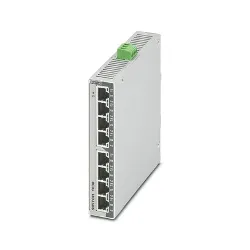 FL SWITCH 1000-8POE-GT - Industrial Ethernet Switch
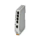 FL SWITCH 1004N-FX SM - Industrial Ethernet Switch
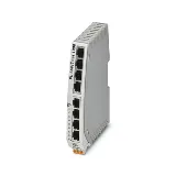 FL SWITCH 1105N-2SFP - Industrial Ethernet Switch


